Uml Use Case Realization Diagram
The Use Case Model
A Use Case Model describes the proposed functionality of a new system. A Use Case represents a discrete unit of interaction between a user (human or machine) and the system. This interaction is a single unit of meaningful work, such as Create Account or View Account Details.
Each Use Case describes the functionality to be built in the proposed system, which can include another Use Case's functionality or extend another Use Case with its own behavior.
A Use Case description will generally includes:
- General comments and notes describing the use case.
- Requirements - The formal functional requirements of things that a Use Case must provide to the end user, such as <ability to update order>. These correspond to the functional specifications found in structured methodologies, and form a contract that the Use Case performs some action or provides some value to the system.
- Constraints - The formal rules and limitations a Use Case operates under, defining what can and cannot be done. These include:
- Pre-conditions that must have already occurred or be in place before the use case is run; for example, <create order> must precede <modify order>
- Post-conditions that must be true once the Use Case is complete; for example, <order is modified and consistent>
- Invariants that must always be true throughout the time the Use Case operates; for example, an order must always have a customer number.
- Scenarios – Formal, sequential descriptions of the steps taken to carry out the use case, or the flow of events that occur during a Use Case instance. These can include multiple scenarios, to cater for exceptional circumstances and alternative processing paths. These are usually created in text and correspond to a textual representation of the Sequence Diagram.
- Scenario diagrams - Sequence diagrams to depict the workflow; similar to Scenarios but graphically portrayed.
- Additional attributes, such as implementation phase, version number, complexity rating, stereotype and status.
Actors
Use Cases are typically related to 'actors', which are human or machine entities that use or interact with the system to perform a piece of meaningful work that helps them to achieve a goal. The set of Use Cases an actor has access to defines their overall role in the system and the scope of their action.
Includes and Extends relationships between Use Cases
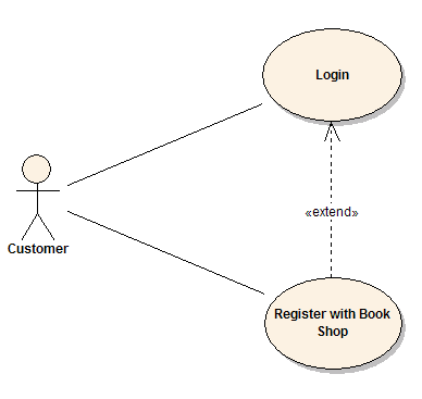
One Use Case could include the functionality of another as part of its normal processing. Generally, it is assumed that the included Use Case is called every time the basic path is run. For example, when listing a set of customer orders to choose from before modifying a selected order, the <list orders> Use Case would be included every time the <modify order> Use Case is run.
A Use Case can be included by one or more other Use Cases, so it helps to reduce duplication of functionality by factoring out common behavior into Use Cases that are re-used many times.
One Use Case can extend the behavior of another, typically when exceptional circumstances are encountered. For example, if a user must get approval from some higher authority before modifying a particular type of customer order, then the <get approval> Use Case could optionally extend the regular <modify order> Use Case.
Sequence Diagrams
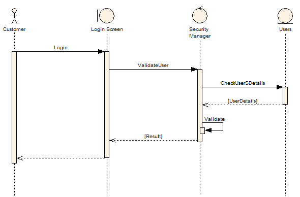
Sequence diagrams provide a graphical representation of object interactions over time. These typically show a user or actor, and the objects and components they interact with in the execution of a use case. One sequence diagram typically represents a single Use Case 'scenario' or flow of events.
Sequence diagrams are an excellent way of documenting usage scenarios and both capturing required objects early in analysis and verifying object use later in design. The diagrams show the flow of messages from one object to another, and as such correspond to the methods and events supported by a class/object.
The following example of a sequence diagram shows the user or actor on the left initiating a flow of events and messages that correspond to the Use Case scenario. The messages that pass between objects become class operations in the final model.
Implementation Diagram
A Use Case is a formal description of functionality that the system will have when constructed. An implementation diagram is typically associated with a Use Case to document which design elements (for example, components and classes) implement the Use Case functionality in the new system. This provides a high level of traceability for the system designer, the customer and the team that will actually build the system. The list of Use Cases that a component or class is linked to documents the minimum functionality that must be implemented by the component.
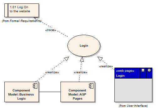
The example above shows that the use case 'Login' implements the formal requirement '1.01 Log On to the website'. It also shows that the 'Business Logic' component and 'ASP Pages' component implement some or all of the 'Login' functionality. A further refinement is to show the 'Login' screen (a web page) as implementing the 'Login' use case. These implementation or realization links define the traceability from the formal requirements, through use cases on to components and screens.
Source: https://sparxsystems.com/resources/tutorials/uml/use-case-model.html
Posted by: cichoszsidnoes.blogspot.com

Posting Komentar untuk "Uml Use Case Realization Diagram"